How Polarized Light Microscopy Works: DIY Setup Guide
By Asha Raman • 23rd Feb
Polarized light microscopy is one of the most revealing optical techniques a home microscopist can adopt, yet it remains underexplored simply because the setup feels intimidating. The mechanics are straightforward: you add polarizing filters to your existing microscope, rotate your stage, and suddenly materials that looked flat or invisible spring into color and contrast. The practical payoff justifies the effort, once you understand how polarized light microscopy works, you'll recognize birefringent specimens instantly and measure optical properties that no standard bright-field setup can reveal.
The Foundation: Light Polarization and Birefringence
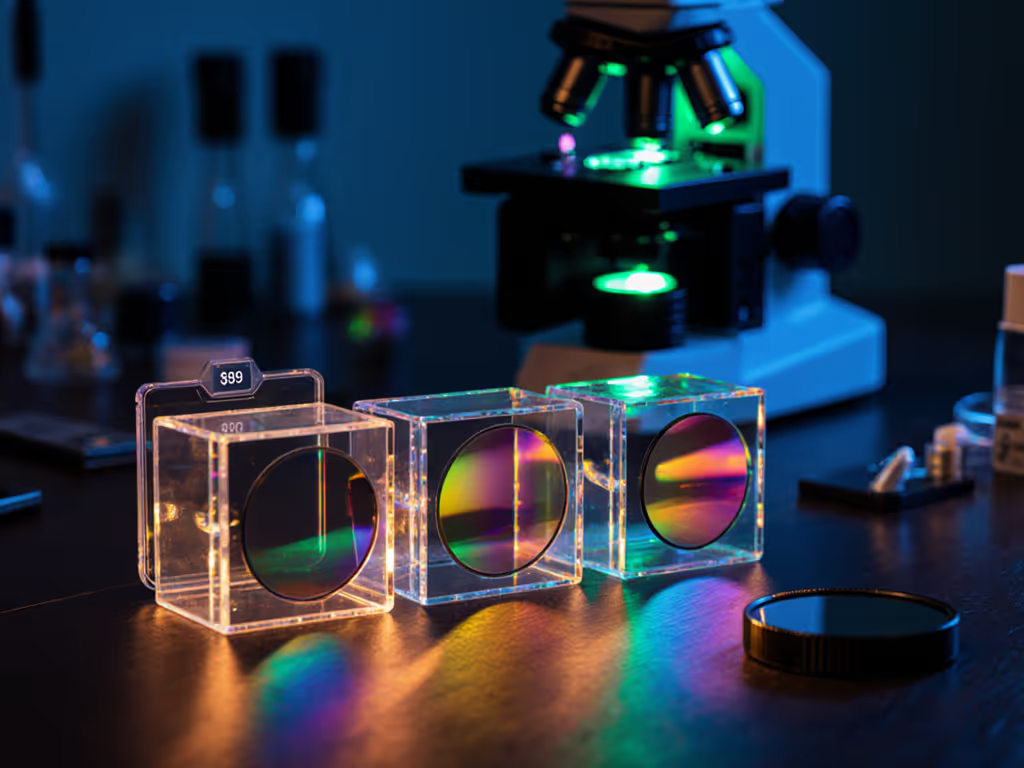
Ordinary light vibrates randomly in all directions perpendicular to its direction of travel. A polarizing filter changes this by selecting and transmitting only light waves vibrating in a single plane, like a fence that only lets vertical posts through. When linearly polarized light encounters a specimen made of anisotropic material (one with different refractive indices depending on the direction the light travels through it), something remarkable happens: the light splits into two orthogonal rays traveling at different speeds. This splitting is called birefringence, and it's the core phenomenon that makes polarized light microscopy work.
Isotropic materials, by contrast, have identical optical properties in all directions. They refract light uniformly, so even when illuminated with polarized light, they produce no useful image contrast. This distinction is your first practical advantage: polarized light microscopy eliminates background clutter, showing you only the structures you're hunting for.
Core Setup: The Two-Polarizer Configuration
Effective polarized light microscopy requires two key optical elements positioned in precise orientation:
| Component | Location | Function | Orientation |
|---|---|---|---|
| Polarizer | Below specimen (usually in condenser) | Produces linearly polarized light | 0° (reference) |
| Analyzer | Above specimen (in turret or tube) | Detects refracted light | 90° (crossed) |
When you set the polarizer and analyzer at 90 degrees to each other (a configuration called crossed polarizers), no light passes through an empty microscope field. The field of view appears black. This dark position is not a bug, it's your baseline. When you introduce an anisotropic specimen, the birefringent material refracts the polarized light, rotating its plane of vibration. Some of that rotated light now aligns with the analyzer's transmission axis and reaches your camera or eyepiece, producing contrast.
Isotropic specimens remain dark under crossed polarizers because they don't rotate the light's polarization plane. This selectivity is what makes the technique so powerful for identifying crystalline materials, oriented polymers, and mineral phases without chemical staining.
Practical Measurement: Rotating the Stage
Once light passes through the analyzer, you can extract quantified data by observing two optical behaviors:
Extinction angles: As you rotate an anisotropic specimen through 360 degrees on your microscope stage, the image alternates between bright and completely dark (extinction) every 90 degrees. The angle at which extinction occurs tells you the orientation of the specimen's optical axis relative to the polarizer. Measuring this across multiple specimens gives you alignment information without a protractor near the sample, pure geometry encoded in light.
Interference colors: When linearly polarized light splits into two orthogonal components inside a birefringent material, the components travel at different speeds. When recombined by the analyzer, they interfere, constructively or destructively depending on their phase difference. This interference produces characteristic color sequences (called the polarization color order) that directly correlate to the optical path difference (OPD), which depends on both the specimen's birefringence and its thickness. For crystalline specimens, this color can be quantified by comparing it to a known interference color chart, giving you a measurable thickness estimate.
DIY Setup: Building Your Polarized System
Converting an existing microscope to perform polarized light microscopy requires minimal hardware. If you need affordable components, our budget polarizing microscope kits comparison outlines filter and rotating-stage options that fit common scopes.
Essential Components
-
Polarizing filter for the light source: Insert this below the specimen (typically in or below the condenser). Linear polarizers for microscopy are precision optical filters, usually HN-type neutral Polaroid filters with polymer films embedded with oriented crystallites.
-
Analyzing filter above the specimen: Place a second identical polarizer in the objective turret, filter cube, or an intermediate tube above the objectives, rotated 90 degrees to the first.
-
Rotating stage: This is not optional if you're measuring extinction angles or interference colors. A circular stage with degree markings lets you rotate the specimen precisely and record the angle of maximum and minimum brightness.
Sample Preparation for Polarized Light
Unlike bright-field microscopy, sample preparation for polarized light is minimal because contrast comes from intrinsic optical properties, not staining:
- Mount your specimen in a refractive-index-matched medium if it's a loose crystal or powder, or leave it dry on a slide if it's already intact.
- Cover with a cover slip if necessary, the coverslip itself is isotropic, so it won't interfere with birefringent signal.
- Place the slide on your rotating stage, ensuring it's centered.
A practical shortcut: many common materials are inherently birefringent and need no preparation. Cellulose fibers (cotton, wood), calcite crystals, aspirin tablets, and even polarizing film itself all light up under crossed polarizers.
Comparing Optical Configurations
Three common polarized light modes offer different information:
| Mode | Polarizer–Analyzer Angle | Viewfield Background | Best For |
|---|---|---|---|
| Crossed polarizers | 90° | Dark (extinction) | Identifying birefringent phases, measuring extinction angles |
| Parallel polarizers | 0° | Bright (pass-through) | General observation; lower contrast |
| Conoscopic (back focal plane) | 90° (with Bertrand lens) | Circular patterns | Measuring birefringence magnitude and optical sign |
In a home setup, you'll rely on crossed polarizers 90% of the time because the dark background provides the highest contrast-to-noise ratio.
Optimizing Your Measurements
Here's where the core practice matters: numbers tell the story; our eyes confirm the practical win. Once your polarizers are in place, measure these quantities:
Dark-field uniformity: Rotate your empty slide between crossed polarizers and photograph the field of view. Count the number of bright pixels; a clean setup should show near zero. If you see bright patches, your polarizers aren't perfectly orthogonal, adjust by rotating the analyzer incrementally until the dark field is truly black.
Extinction contrast: Photograph the same specimen at its brightest (45° rotation) and at extinction (0° or 90°). Calculate the contrast ratio (maximum intensity / minimum intensity). Most well-prepared birefringent specimens yield ratios of 10:1 or higher under crossed polarizers; poor optical alignment drops this to 2:1 or less.
Interference color consistency: If observing the same specimen type repeatedly (e.g., calcite thickness standards), record the color observed and compare it across multiple runs. Consistency within a color order indicates your system is stable; drift suggests a polarizer has shifted position.
These measurements guide your optimization. To ensure your angles and sizes are accurate, follow our microscope calibration guide. If dark-field uniformity is poor, your analyzer might be slightly misaligned, a five-minute adjustment yields measurable gains. If extinction contrast is low, you may need a brighter light source or an optical compensator plate to enhance the signal. Each improvement is quantifiable and reproducible.
Further Exploration
Polarized light microscopy opens doors to mineral identification, polymer orientation studies, and exploring the hidden order in living cells. Your next steps depend on your curiosity and specimens. If you work with crystals, measure birefringence magnitude using a compensator plate and a polarization color chart. For accessory choices tailored to crystal analysis, see our crystallography microscopy accessories guide. If you're interested in natural fibers, extinction angles reveal molecular alignment in textiles and paper. If you observe biological specimens, you'll see collagen organization, muscle striations, and starch granules light up without any dye.
Start with the setup: add two polarizing filters, rotate your stage, and confirm that your dark field is truly dark. Measure your initial contrast ratio on a known birefringent sample, talc powder or a commercial microscope slide works. From there, each specimen you examine teaches you something quantifiable. Your measurements are the foundation; the visual discoveries are the confirmation.
Related Articles